There are three main components needed to deliver the fuel from the tank to the carb; pick up and fuel line, pump, filter. Getting facts about the fuel pumps seems to be the biggest difficulty. The other two items, lines and filters are not quite as bad in this respect. A system should have a regulator as well. However, many mechanical pumps have sufficient control built into the diaphram spring. If this cutoff pressure is below what the carburator's inlet can handle, all is well and the additional regulator can generally be dispensed with.
ON THIS PAGE:
Pump Performance
Pump Fit Issues on Chrysler LA Engines
Some Notes on Lines and Fuel Pick Up
Below is a list of mechanical pumps available for the Chrysler LA
273, 318, 340 and 360 cid engines. The advertised numbers provide
little insight because what is unstated is the test conditions they were
made at. Given no other information, assume the pressure given is the cutoff or
maximum pressure the pump will produce.
* Maximum pressure occurs when
the flow out is zero, so it is most useful in deciding if a regulator is
needed. link: How mechanical pumps regulate pressure.
* The flow advertised is ususally the maximum. Maximum
flow only occurs if the pump was emptying into an open bucket, has no
resistance to drawing on its supply.
* Pump performance is rpm dependent.
We need is to know whether there is sufficient fuel delivery throughout the rpm range the engine is
going to operate with a realistic pressure or resistance in the inlet and
outlet fuel lines. Fortunately, Holley was showing such
information, in addition we sent three pumps to Ryan
Brown
for testing. Testing flow rates at 4.5 psi on the outlet seems to
be reasonable. If tested with 3 psi on the outlet flow rates
should be slightly higher. If the suction side was
restricted, the flow rates will be lower.
|
Brand & Model |
Part Number |
of Valves |
Press. Limit |
Tested
Press.
Limit |
Free Flow (gph) |
(gph) @ 4.5psi |
Maximum Flow @4.5 |
Port size |
Weight |
| Holley | |||||||||
| chrome | 12-838 |
|
7.5 | 80 | failed* | 1/4 npt | 2# 4.5 oz | ||
| 80 gph** | n/a | 7.5 | 80 @2000 | 50 @ 2000 | |||||
| 110 gph | 12-360-11 | 6.5-8 | 110 @5000 | 70 @ 7000 | 1/4 npt | 1# 8.2 oz | |||
| Carter | |||||||||
| stock | 5-7 | 15 @ 500 | |||||||
| Super Street | M6902 |
|
6 | 120 | 1/4 npt | ||||
| Competion | M6270 |
|
7.5 | 7.5 | 80 | 70 @ 6000 | 1/4 npt | 1# 9 oz | |
|
Mopar Perf |
|||||||||
| is a Carter
M6270 |
p4007040 | 7.5 | 80 | ||||||
| p4876074 | |||||||||
| p4529368 |
|
9.5 | 7 | 90 | 71 @ 6000 | 3# 7.5 oz | |||
| with Edelb | bottom plate | 3/8 npt | 3# 9 oz | ||||||
| A graph overlaying our test results and Holley's is below. How
comparable Holley's test procedure and setup is to Ryan Brown's is hard
to know. Clearly they are similar. |
|
Also on the graph is an estimate of the maximum fuel consumption for
the power curve of an engine. This is an estimate for a v-8 that
peaks around 325 hp just over 5000 rpm.
A close approximation of how much fuel is needed at a given rpm is based on these formulas.
1 lbs/hr of fuel required = horsepower /2
gal/hr needed = (lbs/hr /6)
Finally, before making a final decision, use a good safety factor because fuel consumption or the resistance in the flow might be higher than estimated resulting in less fuel actually making to the carb bowls than estimated. This is particularly true during extended high G accelerations such as as drag strip launches.
Max Required is based on horsepower for a 340 bored .060
with Competion Cam's "Magnum 280" cam.
Holley data from Holley Website product info. They also
have (had) good
pump
tech if you can still find it.
Carter and Mopar Performance pump data from testing at
Ryan Brown Racing. New MP P4529638 6 valve pump. Used Carter M6270 'Competition' pump.
Interesting to note that the Holley 80 peaks before
or
at 2000 rpm. (This model was not avail for Chrysler small blocks
but included in graph for comparison with Holley's data for the 110
Pump.)
Clearly the MP six valve pump would be the choice if lots of flow was needed as low as 2500 rpm. Also it would better handle a restrictive fuel system and it had a reasonable cutoff pressure that would not require a regulator with most carburators. However, it has drawbacks in weight and in fit. Fit issues described below. For this reason, we decided to to try a Holley 110 pump. First, its claimed curve (if accurate) is a little better in the mid range than the Carter M6270. Second, our experience had been that the M6270's cutoff pressure of 7.5 psi was just a bit too high. Occassionally this resulted in overfilling the bowls and flooding the carb when demand was low (coasting, idling). Ryan mentioned that the (then) new Holley Kieth Dorton series pumps he has tested were generally pretty good. Anyone dependent on a mechanical pump for racing should consider sending their pumps for testing. Only drawback is the delay in packages going across the US/Canadian border.
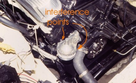 |
Interference problems occur using the six valve Mopar Performance fuel pump and water pumps with passenger side inlet. Note that the inlet sweeps back, but it still clearly possible to fabricate a solution to avoid contact and not restrict flow. The casting nub just barely touches the top of the fuel pump housing and can be ground back to clear. |
| The other problem is that the inlets and outlets are 180 degrees opposite each other. When the inlet faces toward the fuel line from the tank, the outlet faces right into the coolant hose. However, the Edelbrock bottom plate offers a solution using gentle 90degree tube fittings. In the photograph the alternative inlets and outlets are shown. The ones not used can be simply plugged. | 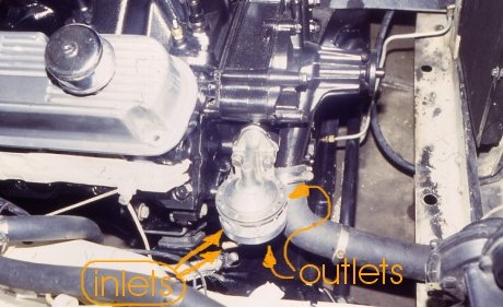 |
Many of the a-bodies used 5/16" fuel line. A good way to minimize the resistance in the fuel lines is to size up. Getting good 3/8" diameter replacement lines is not quite as simple as we'ld all like. First, the lines need to be made in such a way that the bends do not pinch or get oval and reduce the cross sectional area. Second, the clips and fittings need to be changed as well. Third, and perhaps most important, there is not a good source for 3/8" fuel tank pick up for these cars. The pickup is probably the most critical place to increase the fuel line diameter. For the new fuel line, three brands were tried. Only on the third try was the product satisfactory. Inline tube provided a line that was specifically for the '67 and had very little loss of diameter in the bends, the others both had noticible distortion in the bends, and one did not fit the '67 frame in the wheelwell. The first was returned so I don't know if it would have fit.
Serious high horsepower or high G cars should also consider going to braided aircraft line. At least AN-6 will be needed, and many prefer -8. This gets into a whole new area of hooking up AN hose and fittings to a stock fuel tank, or getting a fuel cell.
To convert the fuel sending unit required a little work. At least
in a '67 A-body Plymouth, the original pick up is a different design than
the usual replacement units.
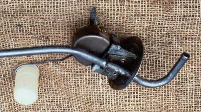
The first attempt is documented below. However it didn't work out
so ended up having to use an aftermarket 3/8 pickup for a later A-body
and plug the opening for a return line,
As best possible, the replacement unit
was made more like the '67 when the 3/8 tube was installed. The sending
unit was disassembled to get it as far from the soldering as possible.
The it was reassembled
and riveted to a bracket.
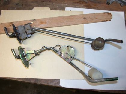
Top. 1967 Pickup and Sending Unit. Bottom. 1968+ Replacement Unit |
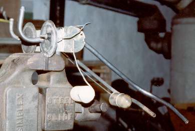
In foreground, replacement unit with 3/8 tube and sender relocated onto intermediate bracket. Trial fit showed that tube did not need to come out as far as shown - an 85 degree angle would have kept it closer to tank and further from axle. |
Home:'67 Barracuda..one
curve to another
More Tech:
Improving Forward Lighting & Electricals
Ignition Wire Comparison
Handling Theory for late-'60s to mid-'70s Mopars
Disclaimer:
If you take advice, or copy something I have done,
you are on your own. I'm just trying to be helpful. You need to make
your own decisions, and know about or discover the risks before barging
ahead on any endevour.
copyright Mathew Grubel, 2003
third edition. Feb 13, 2017